
Network Topology Diagram
A clear network diagram makes it much easier to set up, troubleshoot and hand over a network. Pick a topology to start from, drag devices where you want them, label them with names and IP addresses, add or remove links, and export a clean diagram for documentation or a class assignment.
- Free to use
- No sign-up
- Runs in your browser
Network topology diagram maker
Drag devices to move them. Click a device to select it and edit its label below. In link mode, click two devices to connect or disconnect them.
Network Documentation Pack
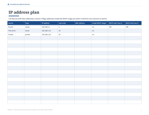
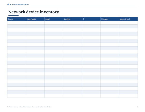
Printable topology reference sheet, an IP address plan spreadsheet, a device inventory template, a network documentation checklist and a blank diagram grid.
- Topology reference (PDF)
- IP plan (XLSX)
- Device inventory (PDF/DOCX/XLSX)
- Documentation checklist (PDF/DOCX)
- Diagram grid (PDF)
Formats: PDF, XLSX, DOCX. Instant download after payment (link valid 72 hours, up to 5 downloads). AI-assisted: the templates were drafted with AI help and reviewed and laid out before publishing.
$3.00 USD, one-time 5 files · about $0.60 each
- Instant download
- 7-day refund
- Secure checkout by Stripe
7-day money-back guarantee. Full refund within 7 days of purchase, even after you download.
Free sample: Blank Diagram Grid (PDF, 99 KB)
Full refund within 7 days — see the refund policy and license.
Free printables
Single sheets you can print right now, no sign-up. The full pack adds every sheet in one download plus the editable files.
 Network Documentation Checklist
 Printable Network Diagram Grid
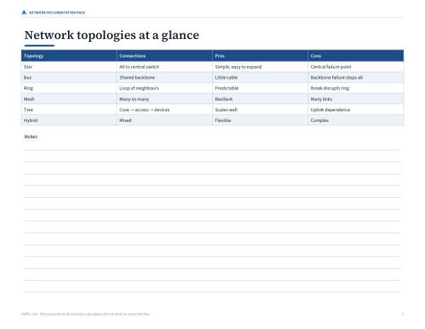
Network topologies compared
| Topology | How devices connect | Strengths | Weaknesses |
|---|---|---|---|
| Star | Every device links to a central switch | Easy to add devices; one cable fault affects one device | The central switch is a single point of failure |
| Bus | All devices share one backbone cable | Little cabling; historic Ethernet (coax) | A backbone break stops the network; collisions; rarely used today |
| Ring | Each device links to two neighbours in a loop | Predictable traffic paths | One break can disrupt the ring unless it is dual |
| Mesh | Devices link to many or all others | Very resilient; many paths | Lots of links: n(n − 1)/2 for a full mesh |
| Tree (hierarchical) | Core switch feeds access switches, which feed devices | Scales well; common in offices and campuses | Depends on upper-level links |
| Hybrid | A mix, e.g. star LAN + Wi-Fi + mesh backbone | Matches real needs | More complex to document |
Most modern wired LANs are physically a star or tree of switches, often with Wi-Fi access points added — which is what the “Small office LAN” starting layout shows.
Full mesh link count
| Devices | Links in a full mesh |
|---|---|
| 3 | 3 |
| 4 | 6 |
| 5 | 10 |
| 6 | 15 |
| 8 | 28 |
| 10 | 45 |
| 20 | 190 |
Because the number of links grows quickly, full meshes are used for small groups of critical routers or in wireless mesh systems, not for every desktop.
Worked example: a small office
An office manager documenting a 12-person office starts from “Small office LAN” with 6 end devices: Internet → firewall → router → office switch, with a file server, printer, backup NAS and three wired PCs on the switch and three laptops on a Wi-Fi access point (shown with dashed links). They rename devices to match the asset tags, type real IP addresses — router 192.168.1.1, file server 192.168.1.10 — drag the printer next to reception, and export a PNG for the IT handover document along with the inventory CSV.
What to include on a network diagram
- Every network device: router, firewall, switches, access points.
- Servers, storage and shared printers.
- Device names and IP addresses (or DHCP ranges).
- Connection types: wired, wireless, uplinks, VPN.
- The internet connection and ISP equipment.
- VLANs or subnets, for larger networks.
- A date and version, so readers know how current it is.
Physical vs logical diagrams
A physical diagram shows where equipment and cables actually are — rooms, racks, patch panels. A logical diagram shows how traffic flows — subnets, VLANs, routing and firewalls — regardless of location. Small networks can combine both on one page; larger ones usually keep separate diagrams. This tool is ideal for small logical diagrams and teaching topologies.
Common home and small-office devices
| Device | What it does | Where it goes on the diagram |
|---|---|---|
| Modem / ONT | Connects to the provider’s line | Between the internet cloud and the router |
| Router | Routes between your LAN and the internet; often runs DHCP | At the edge of the LAN |
| Firewall | Filters traffic by rules | Between internet and LAN (or built into the router) |
| Switch | Connects wired devices in the LAN | Centre of the star |
| Access point | Provides Wi-Fi | Connected to a switch; wireless clients hang off it |
| NAS / server | Shared storage and services | On the switch with a fixed IP |
Many home “routers” combine modem, router, switch and access point in one box — draw it as one device, or split the functions if you want to show how traffic flows.
Troubleshooting with a diagram
- Find the failing device on the diagram and trace its path to the router.
- Check each link along the path — cable, port lights, Wi-Fi signal.
- Compare the device’s IP with the plan to spot conflicts or wrong subnets.
- If many devices fail together, look for the common switch or access point.
- Update the diagram after every change so it stays useful.
IP addressing tips
- Private ranges for LANs: 10.0.0.0/8, 172.16.0.0/12 and 192.168.0.0/16.
- Give routers, servers, printers and NAS devices fixed (static or reserved) addresses.
- Keep a DHCP range for laptops and phones, and don’t overlap it with fixed addresses.
- Record the subnet mask and gateway on the diagram or in the inventory.
Privacy
Diagrams are created in your browser; nothing is uploaded.
Frequently asked questions
What is a network topology diagram?
A drawing of how devices in a network are connected.
What is the most common LAN topology?
A star (or tree of stars) built from Ethernet switches.
How many links does a full mesh have?
n(n − 1)/2 for n devices.
Can I label IP addresses?
Yes — select a device and type its IP.
Can I export the diagram?
Yes, as SVG or PNG, with an inventory CSV.
Is anything uploaded?
No. Everything runs in your browser.
What is the difference between a switch and a router?
A switch connects devices within a network; a router connects different networks, such as your LAN and the internet.
Should I document Wi-Fi devices?
Show access points and important wireless devices; phones can be summarised as a group.
What is a star topology?
A layout where every device connects to one central switch or hub.
Can I use the diagram for homework?
Yes — generate each topology and export it as an image.
Why are some links dashed?
Dashed green links show wireless connections to laptops through the access point.